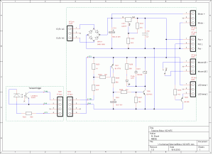
The electronics circuit has several functions. First it has a simple dimmer circuit for the LED light.The pot meter of 500 Ohm linear must be connected to the connector pins Pot+, PotL and Pot-.
The second important circuit is to boost and lengthen the pulses from the ITR8102 to drive a relay. The relay contact is connected to the left button of a cheap USB mouse that will be glued inside the projector. The relay contact is switched in series with the projector main function switch “tape” contacts so that only the mouse pulses are active if the projector is in “play” mode with “tape”.
The new projector DC motor is connected to the motor+ and motor- points via a switch in the remote control box. The motor should then operate at about 16 volts. The transformer that I use is the original transformer, but to increase the voltage on the motor a bit, the mains selection is jumper-ed to 200 volts mains voltage (we have 230 volt where I live). The transformer connection that originally feeded the 100 Watt halogen lamp is now used to feed our circuit and in this arrangement it will output about 13.5 volts.
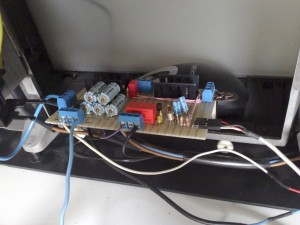
Here is a picture of the circuit board mounted in the projector. Behind the board is the USB mouse glued with double sided tape to the bottom of the projector.
After the wiring is put neatly inside the projector again, the potmeter is placed in the kind of remote control box, we now have the telecine with two USB cables. One more thing, on my remote box I also placed a motor on/off switch. This is very convenient to adjust the projector exactly on the starting point for a new capture. And now, to the film transfer page.

