Introduction
The name of this project comes from it’s purpose, it should be most used on jam sessions in a theater bar for which we deliver a small PA and back-line. The combo should deliver about 45 watts clean power and have overdrive or gain boost. A prototype was build with 2 x EL84 to test various input stages. After a few months of trying several designs the preamp looks like a Dumble Amp because that has a very flexible way to set tone without the amplifier to become to complicated for strangers playing on this amp.
The final amplifier would need to have a bit more power then the 18 Watts of the prototype. The design of the poweramp was given by the fact that I still had a pile of NOS EL34’s and a 45 Watt OT made by Amroh years ago.
The used components came from my personal old stock, a dumpshop nearby (Baco Army Goods), and from Verduin Electronics. I would have liked to order the PT from Hammond, but customs and shipping makes these too expensive here in Europe, so I ordered a toroidal transformer from Amplimo.
Construction
The chassis was made of 2mm aluminum cut from an old traffic sign. This is good quality, not that soft stuff you buy in the local shops.
Years ago when making amps I used to make the front panel letters using wrijfletters and then protect it with a transparent paint. This time I tried a design made with Visio and printed it on sticker paper with a laserprinter. The paper is protected with booklon. The result looks good, but I have to see how it will hold up over a few years.
DC signaling and filaments
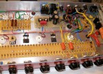
For the overdrive and reverb switching I needed a DC supply for the relays. Also from the prototype I learned that it was best to feed the first three preamp tube filaments with DC too because of the high gain of the preamp. A small power supply was build with a LM117 to deliver a stabilized 12,6 Volt DC. For this purpose a separate toroidal PT was bought from a dump store nearby. The relays are old Siemens relays which have internal shielding between the coil and contacts. On the front is a power led and a run led. The run led is controlled via a transistor from the common cathode of the phase inverter so that it is only on when the HT is on and the tubes are hot. On the picture the 12,6 Volt power supply and wiring for the relays and footswitch.
Build for testing
After the 12,6 Volt DC the power amplifier was build and tested. Since the toroidal PT delivered 325 Volt AC and the OT is only 45 Watts I decided to add an extra sag resistor between the rectifiers and the first filter cap. Later during testing I would decide the final value or leave it out completely. I started using a 130 Ohms resistor.
After the poweramp the preamp was build. The 12,6 Volt DC supply got an extra series resistor before the rectifier because the LM117 becomes too hot. It needs a much larger heatsink.
First tests
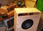
The first tests. It’s a bit crowded in my workshop but I wanted to use the the combo cab that should be used with the Eminence Legend V12 instead of an old monitor box with a 15″ 400 Watt RCF speaker that I normally use to test amps. At this stage the 130 Ohm sag resistor was replaced with a 40 Ohms resistor.
In a dummy load the amp delivers 39 Watts undistorted power. There seems to be a small problem when the amplifier is heavily overloaded. One of the power tubes is increasing current, while the other at some point decreases current after going over a top. The difference will go to about 30 mA while both tubes draw equal current upto a small overload. The cause seems to be the Phase Inverter, this needs some more investigation later. For the rest the amp sounds good with the crappy guitar I have in the workshop.
The cabinet
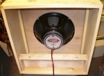
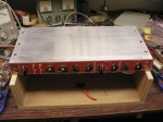
The picture on the left shows the blank cabinet. The boxed space in the downside will be used to mount the reverb tank.
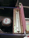
The picture on the right side shows how the reverb tank folded in an air filled packaging material. This provides a good mechanical isolation. I used this as alternative for the usual bag that you normally find in combo cabinets.
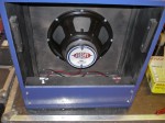
The picture on the left shows the cabinet with the closed reverb tank enclosure.
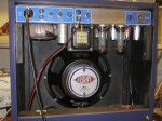
On the right side, the chassis with a shielding plate. This is just a thin plate of aluminum that just lies on top of the chassis.
The final result
On the left the amplifier is mounted in the cabinet. The tube protection board is not yet installed.
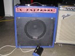
On the right, the completed amp is on stage next to a 1972 Twin Reverb.
Schema and clips
Here are the schematics and construction drawings.
| Name | Date | Size | Hits |
|---|---|---|---|
| Name | Date | Size | Hits |
| ESR meter.pdf | 10-Oct-2011 | 36.9 KiB | 4771 |
| T-Jam 45 Chassis.pdf | 04-Oct-2011 | 206.7 KiB | 951 |
| T-Jam 45 Schema.pdf | 04-Oct-2011 | 110.9 KiB | 1594 |
| T-Jam 45 Wiring.pdf | 04-Oct-2011 | 162.8 KiB | 995 |


